


September 11, 2019
How To Service French Horn Rotors
With a few simple, affordable supplies and this step-by-step guidance, musicians and music directors can easily learn to service rotor valves. This can be of great benefit in both emergen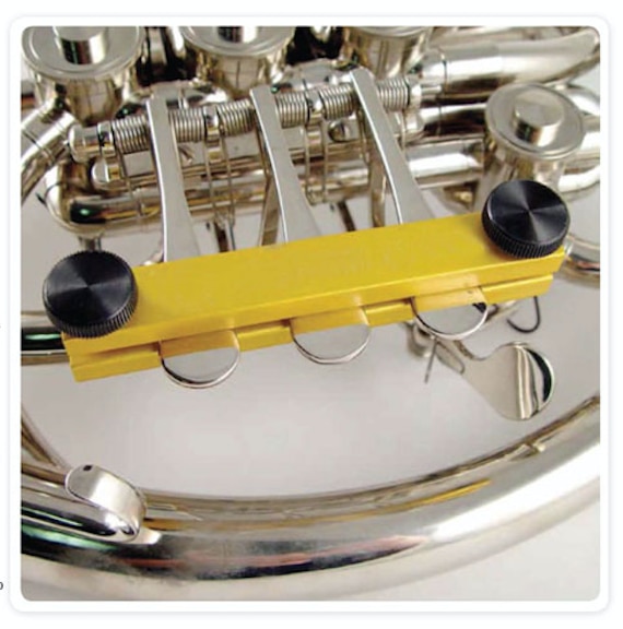 cy situations and as a matter of regular maintenance. While there are many points of service that can be attended to without great investment or advanced skill, there are still many areas of repair (beyond the scope of this article) that must be referred to professional technicians.
Cleaning and Lubrication
As a musical and mechanical necessity, rotor valves have a very tight clearance between the rotor and valve casing and at the bearings. Because of this, any deposits on any part may cause the valve to lock in place or freeze up. This is most likely to be experienced after the instrument has been unused for some time.
Playing the instrument daily tends to keep minerals and lubricants from hardening into deposits. This is particularly true if the musician lubricates the rotors frequently. The lubrication helps the valve shed any contaminants, and fills the space that would otherwise attract water-born minerals, which create deposits.
Often you can free a stuck or sticking valve without disassembly by lubricating the rotor through the slide tubes, and working the rotor stop arm back and forth by hand. Pulling the valve slides, put two drops of valve oil into each tube on the horn. Don’t turn the valve using the levers, but rather by directly turning the stop arm (fig. 1). Also put a drop on the back bearing (after removing the cap), and the top bearing (beneath the stop arm).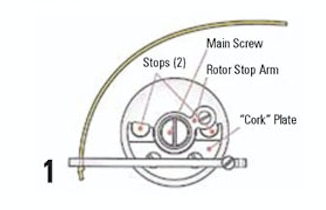
To clean a valve requires disassembly. First unscrew and remove the valve caps. If these are frozen, tap lightly on the knurled (grip) area of the cap in a glancing counter-clockwise manner (as if trying to unscrew the cap). If the cap is still stuck, apply a drop of penetrating oil to the joint of the cap and casing, and try again after the oil has been allowed to penetrate.
Loosen the main screw a turn or two, and tap on the screw to release the road or from the bearing. Completely unscrew the main screw allowing the rotor to be pulled from the casing. If you are removing more than one valve at a time, keep them in order so that you can get the router in the correct casing when reassembling.
Protect the rotor by working over a table covered with a soft towel to receive the rotor if it falls. Also protect the bell stem of the instrument so that if a lever arm releases, the spring tension won’t slam the lever into the bell causing a dent. Control the levers while tapping the rotor loose.
The rotor is now available for cleaning. While a scrubbing in soap and water may bring results, more often you will need to soak the rotor in a chemical to remove deposits. White vinegar is a good solution for the non-professional. You may wish to pull all the slides and rotors and give the instrument a brush through in a bath of lukewarm water and mild dishwashing detergent. Rinse thoroughly, and allow to dry before assembling with fresh slide grease and valve oil.
Cleaning the valve casing of deposits is problematic because it requires a larger tank of solution. I would refer this to a technician. Many professional shops use ultrasonic cleaners and more aggressive chemicals for this task.
Wiping both the casing and the rotor with a lint-free cloth, dry test the fit of the rotor. If you are satisfied that the valve rotates freely, reassemble the valve with fresh oil, adding a drop of rotor oil on the bearings and the threads of the valve. Place the stop arm back onto the rotor and set the main screw. Be careful not to over tighten the screw. This task can be clumsy if the string is still attached. You may wish to detach the string and restring it after assembly.
Adjusting rotor port alignment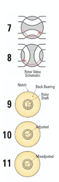
- In order for the instrument to play its best, it is necessary that the rotor valve ports align correctly with the tubing to which they direct the airflow to Figure 7. Taking the valve cap off the rotor, you will see corresponding marks in both the rotor shaft and in the back bearing. You will also notice a small notch on the outer edge of the back bearing Figure 9. Align the notch in the back bearing with the corresponding notch in the valve casing. This bearing is gently pressed into place. If it is not located correctly, loosen the stop arm main screw (figure 1) a couple turns. Tap on this screw to release the back bearing, rotate the bearing to its home position, and tap it back into place. Reset the main screw. Note when securing the bearing, it is best to use a plastic tube or a dowel with a center hole, which fits over the center of the bearing. Tap on this tube to equally distribute the pressure applied by the hammer.
- Moving the rotor stop arm all the way in each direction, observe the position of the mark in the rotor in relation to the mark in the bearing. These must align perfectly when at each stop (figure 10 and 11).
- This alignment is adjusted by changing the size of the rotor stops. The rotor stops are often neoprene, sometimes cork. The JLS kit includes neoprene. Use this to replace stops that are missing or too small to be adjusted. If the stop is too large, it can be cut back with a razor blade.
- While it may be possible to insert new stops while all parts are assembled, it sometimes is necessary to remove the cork plate from the casing, making it a bigger job. The stop material often needs to be squeezed with pliers or stretched to fit into the plate. The material within expands to fit securely in the cork plate. If you remove the cork plate, you can hold one end of the neoprene in a vice, which easily allows you to stretch the material and insert it into place. Trim the excess on each side of the plate with a razor blade.
 Restringing Guide
These instructions include the use of the JLS206058 valve restringing kit
- Set the stringing jig in place over the lever touch pieces as shown. This will keep all levers on plane with each other. Note if all valves are being restrung, you will determine the touch piece height when you secure the first screw in step six.
- Loosen the rotor stop and the lever string screws and remove the old string. Don’t loosen the screws more than enough to remove the old string, we don’t want to lose them.
- Cut a new piece of string about 8 inches long.
- Tie a knot in one end. This will act as a stopper to keep the string from pulling through, so make the knot larger than the hole in the lever arm.
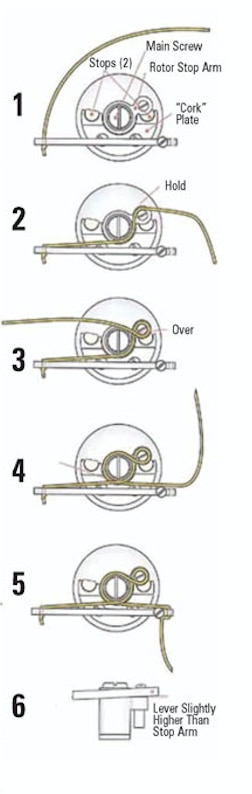
- Thread the string through the hole as shown in figure 1. Tip: if you cut the string at an angle you can pass it through the hole easier. Use a sharp razor blade to make this cut.
- Holding the rotor arm in the position shown, wrap the string as in figure 2, making sure that the string goes under the screw. Continue wrapping as shown in figure 3. Secure the screw and don’t over tighten.
- Continue with the string as in figure 4, then take it through the hole as in figure 5 and wrap it under the screw. Secure the screw.
- When at rest, the arm of the lever will usually be set at an elevated angle to the rotor so that when the lever is pressed the arm won’t be too low, which can cause binding and noise (figure 6). It may be necessary to realign the lever arm to the touch piece. The alignment is performed by holding the touch piece and bending the end of the lever either up or down. The lever ends should all be on plane with each other just as the touch pieces were.
- To add a professional touch, clip the ends of the strings so that they are the same length. To allow for possible adjustment later, leave the unknotted end at least 3/4 inch long.

